
An engineering guide comparing COF and COG for industrial OLED durability, signal integrity, optical coupling, EMI resilience, repairability, test strategy, and procurement decisions.
Industrial robotics is changing what matters in display design. For consumer phones we chased thinner bezels, higher peak luminance, and marginal gamut gains. For robots — industrial manipulators, AMRs, vision-assist terminals, and maintenance HMI — the design priorities shift toward robust packaging, signal integrity, repairability, and optical coupling stability. That is why the packaging choice for small OLEDs — COF versus COG — has become the frontline of a practical packaging war in 2025.

1) Why Packaging Matters for Industrial OLEDs
Packaging is more than mechanical protection. It influences electrical interconnect behavior, thermal dissipation, module stress tolerance, and how accurately the display delivers color and timing into optical systems such as waveguides, combiners, and magnifiers. In robots, these characteristics map directly to safety, visual correctness, and uptime.
Industrial OLED usage differs from consumer use in several important ways:
- 24/7 operation and different lifetime and aging patterns
- Vibration, shock, and repeated flexing in mobile or articulated systems
- Harsh EMI exposure near motors, drives, and power electronics
- Tight optical coupling to sensors or waveguides where timing and angular color matter
- Maintenance models that require modular repair and field replacement
Packaging choice directly changes how the module behaves under each of these constraints.
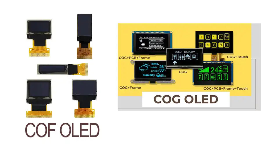
2) Quick Primer: What Is COF and What Is COG?
2.1 COG — Chip-On-Glass
COG bonds the driver IC directly to the display glass or glass-like substrate. This enables a thinner optical stack and a short thermal path from the IC to the glass, which is useful when optical thickness and heat spreading are priorities.
2.2 COF — Chip-On-Film
COF mounts the driver IC on a flexible film that then connects to the glass through bonded traces or an interconnect structure. The flexible routing provides mechanical compliance, helps absorb shock and vibration, and creates room for shielding or extra circuitry.
3) What Robots Changed in 2025
Robotics systems now operate in more complex environments, integrate more sensing, and face stronger uptime requirements. These realities push OEMs and integrators to demand capabilities that consumer display projects often overlook:
- Survivability under cyclical mechanical stress
- High-fidelity optical coupling
- Electromagnetic robustness
- Field serviceability
- Reliability at temperature extremes
For many robot applications, a display that survives vibration and can be replaced in the field is more valuable than one with the thinnest possible stack.
4) The Invisible War: Signal Integrity and Timing
Packaging debates often focus on mechanical or thermal behavior, but in robot systems the electrical story is equally important. HMI and vision overlays depend on fast serial interfaces and precise timing. COF and COG create different SI, skew, and jitter challenges.
4.1 Common SI Failure Modes in Industrial OLED Modules
- Propagation delay imbalance caused by uneven trace routing
- Reflections and impedance mismatch at interconnect transitions
- EMI pickup from nearby motor drives or switching supplies
- Timing jitter that produces corruption or visible tearing
4.2 Why This Matters to Robots
Robot HMI often overlays live sensor data, path heatmaps, and temporal telemetry. Even small timing or color skew can misrepresent safety-critical information. In these systems, SI failure is not just cosmetic — it can become hazardous.
5) Mechanical and Thermal Behavior: Why Robots Often Prefer COF
COF’s flexible interconnect absorbs micro-movements. In a robot arm where cable routes flex continuously, a COF design with good strain relief often outlasts a rigid COG bond. COF also improves modular repair by allowing driver or flex replacement without replacing the full glass unit.
5.1 Vibration and Impact
COG’s direct bond is mechanically stiff. Repeated high-G events can propagate stress into bump or solder interfaces and eventually to the glass itself. COF’s flex reduces transmitted stress and often performs better in long-term vibration environments.
5.2 Heat Dissipation
COG provides a shorter thermal path from IC to glass and then to chassis, which can help when drivers run hot or high brightness is needed. COF is less thermally direct, but good carrier design, copper planes, or thermal interfaces can compensate.
| Attribute | COG | COF |
|---|---|---|
| Mechanical compliance | Poor | Excellent |
| Field replaceability | Poor | Excellent |
| Thermal path | Better | Good with design |
| Module thickness | Thinner | Thicker |
| SI complexity | Lower | Higher |
6) Optical Coupling, Waveguides, and Color Consistency
Many industrial robots integrate displays with optical injection systems such as waveguides, inspection scopes, or combiners. Packaging affects optical thickness, alignment repeatability, and angular color behavior.
- Stack thickness is usually an advantage for COG.
- Mechanical repeatability after service is often an advantage for COF.
- Micro-bending risk in poor COF layouts can create edge artifacts or color shift.
If the module couples into a waveguide, measure angular ΔE and pixel timing after installation and again after mechanical stress cycles. Issues that look small on a bench can become obvious through optics.
7) Case Studies
7.1 Robotic Arm Teach Pendant
A compact teach pendant with frequent drops, strong vibration, and a long field service model favored a COF-based OLED module with reinforced strain relief, EMI shielding, and modular connection. The result was lower repair cost and higher field MTBF than a COG alternative.
7.2 AMR Fleet Dashboard
A mobile robot HUD requiring sunlight-readable navigation overlays used a hybrid architecture: a thin COG micro-module for optical injection combined with a COF carrier that handled EMI and thermal management. This balanced optical thinness with flexible connectivity.
7.3 Vision-Assist Scope for Surgical Robotics
A surgical system requiring very stable color, tight alignment, and predictable thermal behavior selected COG with a precision glass-to-chassis thermal path and hermetic encapsulation. Serviceability was lower, but optical stability was best-in-class.

8) Procurement and Engineering Checklist for Robot OEMs
Use this checklist when evaluating OLED modules for robotics:
- Request angular ΔE data before and after vibration cycles.
- Require MIPI or LVDS eye diagram and BER testing after module integration.
- Ask for thermal cycling and 24/7 operation reports.
- Verify EMI susceptibility near motor-drive switching conditions.
- Check field repairability and spare-part strategy.
- Confirm optical-coupling tolerances for waveguide or combiner use.
- Ask for fade curves and yellowing metrics at expected operating temperatures.
9) Recommended Design Patterns and Mitigations
9.1 If You Choose COF
- Use matched-impedance traces with minimal practical routing length.
- Add local buffering if jitter or lane skew becomes a concern.
- Implement mechanical strain relief and control bend radius carefully.
- Add shielding, ground structures, and common-mode filtering where needed.
- Provide robust, field-friendly connector orientation and swap design.
9.2 If You Choose COG
- Use compliant mounts and damping to reduce stress transfer to bump bonds.
- Provide replaceable chassis subassemblies if serviceability matters.
- Use strong thermal interfaces for high-brightness or hot-driver operation.
- Focus fatigue testing on thermal cycling combined with mechanical shock.
9.3 Hybrid Approaches
A hybrid approach — COG for optical thinness and COF as an intermediate carrier for flexibility and buffering — often provides a balanced solution. This pattern is becoming increasingly attractive in AMR and advanced industrial designs.
10) Testing Strategies Robot Integrators Must Require
Beyond typical consumer tests, robot programs should require:
- 3D light-field consistency testing
- Integrated SI validation at module level, not just panel level
- EMI susceptibility validation near representative industrial equipment
- Serviceability cycle testing
- Thermal aging with optical measurement
11) Market and Supply Chain Implications
The packaging split affects supply chains as well:
- COF depends on strong flexible PCB and fine-pitch film bonding capability.
- COG depends on precision bump-bonding, glass handling, and encapsulation lines.
- Driver IC vendors are optimizing packages for both routes.
- Module integrators are increasingly offering hybrid carriers to reduce custom tooling burden.
Expect a split market: mid-volume industrial OEMs often lean toward COF modularity, while optical-critical or medical systems continue favoring COG stability.
12) Conclusion — Choose for the Robot’s Reality, Not the Display Sheet
By 2025, the display conversation in robotics is no longer just about brightness. It is about whether the module can survive the robot’s physical and electromagnetic environment while preserving timing, color, and serviceability.
- Choose COF when mechanical resilience, field replaceability, and EMI mitigation matter most.
- Choose COG when optical thinness, direct thermal path, and stable color in controlled environments dominate.
- Consider hybrid designs when you need both optical precision and service flexibility.
FAQ
Q1: Can software fix timing skew and color shift introduced by COF?
Software can compensate for small lane-delay or color-angle errors, but it cannot fully recover from large physical routing mismatches, reflections, or permanent mechanical damage. Hardware integrity remains the priority.
Q2: Which packaging is cheaper?
That depends on volume, architecture, and service model. In industrial volumes, total cost of ownership — including downtime and repairs — is often more important than the initial module price.
Q3: Is hybrid always the best?
Not always. Hybrid designs can balance tradeoffs well, but they add BOM complexity and supply-chain dependence. They must still be validated carefully for SI and mechanical behavior.
Q4: What tests should I insist on?
Require module-level BER and eye-diagram testing, angular ΔE mapping, thermal aging with optical measurement, vibration and shock endurance, and EMI immunity tests matched to the robot environment.
Q5: How quickly will the packaging landscape change?
Expect gradual change through 2025 to 2027, with broader COF use in modular industrial designs, continued COG strength in optical-critical systems, and growing hybrid adoption where both benefits are needed.

Hinterlasse einen Kommentar
Diese Website ist durch hCaptcha geschützt und es gelten die allgemeinen Geschäftsbedingungen und Datenschutzbestimmungen von hCaptcha.