
A practical selection framework covering readability, reliability, power, lifespan, calibration, and industrial integration priorities.
1) One-Page Quick Standard
Priority order for industrial OLED: Readability > Reliability > Power/Lifespan > Cost. Readability is not peak nits. It is contrast cone, total reflectance, and polarization compatibility working together.
Selection Dimensions
- Readability: contrast cone, total reflectance ≤1.5%, polarization tolerance
- Reliability: temperature, humidity, vibration, shock, EMC, chemical resistance
- Performance: typical luminance, MPRT, white-point stability, image retention
- Power: LTPO and low-refresh stability, standby draw
- Lifespan: L80 target, burn-in mitigation, aging map
- Integration: interface, driver IC, touch, cover, stack-up, tolerances
- Calibration: 3D LUT, zone LUT, temperature compensation, online compensation
Suggested Thresholds
2) Why This Guide
In bright factories or outdoor yards, pushing peak luminance alone rarely solves readability. Reflections, glare, and viewing-angle shifts often dominate. OLED’s native contrast becomes true legibility only when matched with the correct optics, drive method, and calibration strategy. This guide is designed to help procurement and engineering narrow to a shortlist within one day.
3) Panel Selection: Win with the Contrast Cone
3.1 Readability Beats Peak Nits
The contrast cone represents usable contrast across viewing angles under fixed illuminance. For outdoor or near-window stations, use 10,000 lux as an acceptance condition and require at least 3:1 contrast within ±30° at equal power budgets.
- Method: set 5k and 10k lux, display black, white, and gray patches, then measure contrast over angle.
- Acceptance: a larger cone area at the same power budget means better readability with less thermal and battery burden.
3.2 Total Reflectance and Surface Finish
Even excellent OLED blacks can wash out under glare if the optical stack reflects too much. Target total reflectance of the full stack at ≤1.5% and control haze to avoid sparkle and text blur.
- Coating baseline: AR plus AF.
- In oily or dusty sites, low-haze microstructures are often better than aggressive AG treatments that soften text.
3.3 Polarization Compatibility
Industrial users may wear polarized eyewear, and windows or shields may introduce additional polarization. Require visibility under linear and circular polarizer conditions without severe extinction or large color shifts.
- Test: rotate a linear polarizer from 0° to 180°, then record luminance and color shift.
- Suggested pass: luminance remains ≥50-60% of baseline and ΔE00 stays within 3-5 across rotation.
3.4 Cover and Mechanical Integration
Select the cover material according to the real chemical and impact environment. Glass often fits coolant, alcohol, and oil exposure best when paired with AF coating and proper sealing. Thickness must balance impact resistance against parallax, reflectance, and assembly stress.
4) Driver and Power: Cut Draw, Flicker, and EMC Issues
4.1 Interfaces and Timing
MIPI DSI and parallel or SPI interfaces dominate small and mid-size industrial HMI products, while eDP is more common for larger dashboards. Check supported refresh range and low-refresh dimming behavior carefully.
4.2 LTPO and Smart Power
LTPO allows deep refresh-rate reduction for static screens and can save substantial power. However, very low refresh combined with low-frequency PWM can create visible flicker.
- Combine low refresh with DC dimming or high-frequency PWM.
- Use regional brightness adaptation so alarm areas stay bright while secondary tiles dim.
4.3 MPRT for Motion Clarity
Industrial UI often includes live plots, moving tickers, and flashing alerts. Target MPRT ≤8 ms. Overdrive or black frame insertion may help, but these should be balanced against power and EMC side effects.
4.4 EMC and EMI Hardening
- Layout: keep high-dv/dt nodes away from high-speed lanes and length-match critical pairs.
- Filtering: use π filters on power rails and common-mode chokes where needed.
- Validation: run quick field smoke tests near VFDs or switchgear and watch for snow, tearing, or touch false triggers.
4.5 Hazardous Area Design
For explosive or hazardous environments, manage energy limits, isolation, and surface temperature carefully. The OLED module and the full system architecture must be aligned with the applicable intrinsic safety scheme.
5) Calibration and Quality
Factory Calibration
Factory calibration reduces cross-batch mismatch and visible drift.
- Suggested targets: white ΔE00 ≤2 and luminance uniformity ≥85-90%, depending on size.
- Use 3D LUT or tiled zone LUT approaches if angular and spatial variation are meaningful.
Online and Temperature Compensation
Use onboard thermal sensing with color and brightness compensation. Implement temperature-based brightness back-off to protect lifetime and reduce color drift.
Aging and Image Retention Management
- Maintain aging maps and schedule equalization cycles.
- Nudge static UI elements and rotate accent positions over time.
Traceability
Track panel serial number, calibration version, total on-time, and major thermal events to improve serviceability and warranty clarity.
6) Reliability and Environment
Thermal, Humidity, Vibration, and Shock
Use environmental test regimes that include thermal cycling, damp heat, random vibration, and mechanical shock. Automotive system-level practices can provide useful guidance, especially around connector fretting and frame stress.
Chemicals and Dust
Qualify covers, coatings, and seals against oils, coolants, disinfectants, and salt mist. IP protection and debris management reduce heat spots caused by dust buildup.
High Illuminance
Validate readability at 10,000 lux or higher using contrast cone measurements and read-error testing. Avoid relying on luminance numbers alone.
Electromagnetic Environment
VFDs, radios, and high-power switchers can combine to produce snow, resets, or touch drift. Shield continuity and chassis bonding are just as important as PCB fixes.
7) UI and Human Factors
Typography and Iconography
- Use slightly bolder weights for bright environments.
- Minimum effective stroke width should remain readable under glare.
- Align thin strokes carefully to reduce fringing.
Safety Colors and Alerting
Red, amber, and green states must remain distinguishable under glare. Define minimum luminance and contrast thresholds for alert colors.
Glare and Blue-Light Hygiene
Night modes should adjust luminance and chromaticity smoothly, reduce high-contrast hotspots, and avoid abrupt changes when entering dark spaces.
8) One-Day Decision SOP
Step 0: Requirement Card
- Scene and illuminance: indoor, outdoor, near-window, 5k or 10k lux
- Thermal range and life target
- Interfaces, size, bezel, tolerances, and power budget
- Compliance needs including EMC or hazardous-area requirements
Step 1: Datasheet Sweep
Discard models that lack critical parameters. Request any missing data such as total reflectance, contrast cone, polarization behavior, PWM and MPRT, lifetime model, and retention strategy.
Step 2: Rapid Sample Tests
- Bright-light readability using contrast cone and black-screen reflectance checks
- Polarization sweep from 0° to 180°
- Glove operation and touch false-trigger sanity checks
- EMC smoke test near VFDs or switchgear
Step 3: Scoring and Decision
Use a weighted model: Readability 40%, Reliability 30%, Power 15%, Cost 15%. Set hard stop thresholds for reflectance, contrast cone, flicker, and polarization extinction.
Step 4: Pilot and Acceptance
Run thermal cycling, vibration, chemical exposure, and real-station trials. Log color drift, brightness drift, and online-compensation effectiveness.
9) Copy-and-Use Core Targets
| Metric | Suggested Target | Why It Matters |
|---|---|---|
| Total reflectance | ≤1.5% | Prevents OLED blacks from washing out under high lux. |
| Contrast cone @10,000 lux | ≥3:1 within ±30° | Predicts real-world readability across angles. |
| Typical luminance | ≥800-1200 nits | Usually sufficient when paired with low reflectance. |
| MPRT | ≤8 ms | Improves motion readability and reduces misreads. |
| Operating temperature | -30 to +85 °C | Covers harsh industrial environments. |
| White ΔE00 | ≤2 | Improves batch consistency and service swap quality. |
| Lifespan | L80 ≥20-30k h | Supports long service life with thermal back-off. |
| Power and dimming | LTPO supported; no obvious low-Hz flicker | Supports comfort and efficiency on static dashboards. |
| EMC performance | Target class pass plus field smoke-test pass | Improves stability near noisy industrial equipment. |
10) FAQ
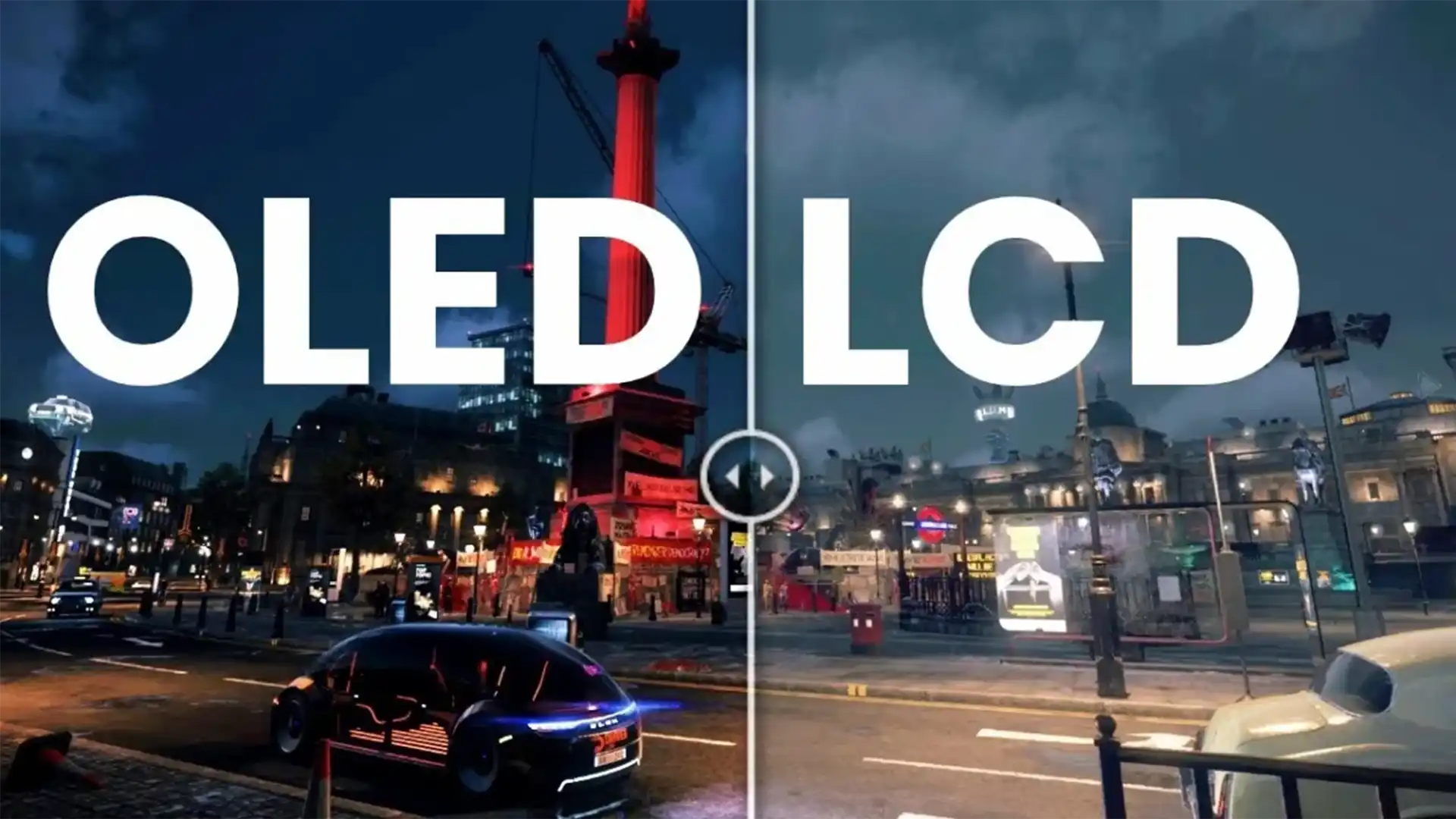
Is OLED always clearer than LCD in sunlight?
Not always. The optical stack matters most. With low reflectance and a strong contrast cone, OLED often wins on real-world legibility.
Is LTPO stable for industrial use?
Yes, if combined with DC dimming or high-frequency PWM and validated under the expected EMC environment.
How should burn-in be mitigated?
Use aging maps, equalization cycles, UI drift, and thermal or brightness back-off policies with clear retention acceptance criteria.
What about hazardous areas?
Intrinsic safety must be engineered at the system level through energy limits, isolation strategy, and enclosure thermal control.
How should low-temperature startup flicker be handled?
Use a controlled warm-up current and time strategy, avoid very low PWM frequencies, and blend DC dimming where possible.
What are the key EMC practices for OLED HMIs?
Use short return paths, solid reference planes, shield terminations, supply filtering, chassis bonding, and disciplined touch grounding.
11) Common Pitfalls
Brightness without reflectance control: this often creates washed blacks and a brighter but less readable display.
Ignoring polarization: screens may dim or shift color under sunglasses or laminated windows.
Low-Hz flicker from power saving: LTPO combined with low-frequency PWM can create discomfort.
No chemical validation: AF and AR coatings may fail quickly in coolant or alcohol exposure.
No online compensation: white drift and retention accumulate until pilot or acceptance stage.
12) Comparison Snapshot
Same power, bright-sun test example:
- Scene: 10,000 lux, ±30° viewing
- High-nit LCD: 1,600 nits, about 4% reflectance, contrast cone below 2:1
- Low-reflectance OLED: 1,000 nits, 1.2% reflectance, contrast cone at or above 3:1
- Outcome: faster alarm-icon recognition and fewer read errors
Lesson: lower reflectance plus a stronger contrast cone can beat raw brightness for real daytime legibility.
Hinterlasse einen Kommentar
Diese Website ist durch hCaptcha geschützt und es gelten die allgemeinen Geschäftsbedingungen und Datenschutzbestimmungen von hCaptcha.