
Introduction: Choosing the right display module is only half the battle. The invisible data pipeline connecting your microcontroller (MCU) to that screen—the interface—determines whether your product feels snappy and premium, or sluggish and cheap. In this comprehensive engineering guide, BROWNOPTO breaks down the four dominant OLED interfaces to help you make the perfect choice for your next embedded project.

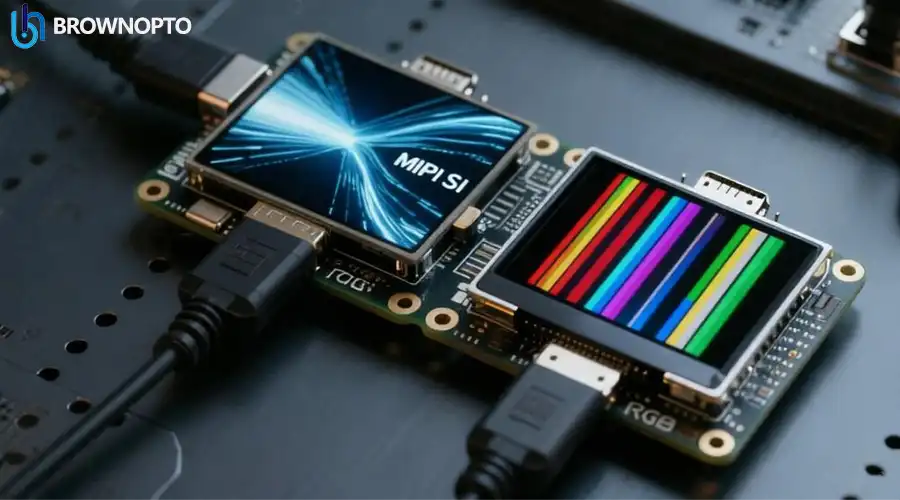
Figure 1: The physical complexity difference between low-speed and high-speed interfaces.
The "Iron Triangle" of Display Engineering
Before selecting an interface, every engineer must balance three competing factors:
- Bandwidth (Frame Rate): How much data needs to move? A 4K video requires gigabits per second; a static temperature reading requires bits per second.
- GPIO Usage (Pin Count): How many pins can you spare? An ESP32 has limited pins; an STM32H7 has hundreds.
- Power & Complexity: High-speed interfaces like MIPI require complex impedance matching on the PCB, whereas I2C works on a breadboard.
1. I2C (Inter-Integrated Circuit)
The "Minimalist" Choice for Wearables and Sensors.
I2C is a serial protocol that uses only two wires: SDA (Data) and SCL (Clock). It is a bus protocol, meaning you can daisy-chain multiple sensors (temperature, accelerometer) and the OLED display on the exact same two wires, provided they have different addresses.
Best For:
• Small displays (0.49" to 0.96")
• Text-only interfaces or static icons
• Pin-constrained MCUs (ATTINY, ESP8266)
2. SPI (Serial Peripheral Interface)
The Industry Standard for Small-to-Medium Color Screens.
SPI is significantly faster than I2C because it uses a "Push-Pull" driver architecture. It can easily reach speeds of 10MHz to 50MHz. In the OLED world, we typically use 4-Wire SPI.
Why 4-Wire SPI? (The "D/C" Pin)
Standard SPI uses MOSI, CLK, and CS. However, OLEDs add a 4th wire: D/C (Data/Command).
This pin physically tells the display controller: "The byte I am sending now is a pixel color" (High) or "The byte is a configuration setting" (Low). This hardware switching is much faster than software decoding, allowing for higher frame rates.

Best For:
• Smart Home Thermostats (1.5" - 2.4")
• Smooth UI animations (30-60 FPS)
• Industrial handheld devices
3. MCU Parallel (8080 / 6800)
The "Brute Force" Solution for Legacy Systems.
Before high-speed serial interfaces became cheap, Parallel was king. It transfers data 8, 16, or 18 bits at a time. It is like a multi-lane highway compared to the single-lane road of SPI.
The Trade-off: It is incredibly pin-hungry. An 16-bit parallel interface requires: 16 Data pins + CS + RS + WR + RD + Reset = 21 GPIO pins. This makes PCB routing a nightmare for small devices.
Best For:
• Medical equipment using older processors
• Scenarios where the MCU has a dedicated FSMC (Flexible Static Memory Controller)
• Large, low-resolution industrial panels
4. MIPI DSI (Display Serial Interface)
The Future of High-End Displays.
If you are building a VR headset, a smartphone, or a high-end automotive dashboard, you need MIPI. It uses Low-Voltage Differential Signaling (LVDS) to transmit data at incredible speeds (1 Gbps per lane) with very low power consumption and low electromagnetic interference (EMI).

Best For:
• High Resolution (720p, 1080p, 4K)
• High Refresh Rates (90Hz, 120Hz)
• Video playback applications
Comparison Matrix
Use this table to match the interface to your project constraints.
| Feature | I2C | 4-Wire SPI | MCU Parallel (8080) | MIPI DSI |
|---|---|---|---|---|
| Pin Count | Lowest (2 Pins) | Medium (5-7 Pins) | Very High (15-25 Pins) | Medium (4-10 Pins) |
| Max Speed | ~400 kHz | ~50 MHz | ~20 MHz (x16 width) | 1.5 Gbps+ (Per Lane) |
| Video Capable? | No | Limited (Low Res) | Yes (Medium Res) | Yes (4K/HD) |
| Noise / EMI | Low | Medium | High (Switching Noise) | Very Low |
| Typical Size | < 1.0 inch | 1.0 - 3.5 inch | 2.4 - 5.0 inch | 3.0 - 10+ inch |
Customization: Can I Change the Interface?
This is the most common question we receive at BROWNOPTO. The answer is: Yes, usually.
Most OLED Driver ICs (like the SSD1306 or SH1106) actually support I2C, SPI, and Parallel on the silicon level. The specific interface is selected by the wiring on the FPC (Flexible Printed Circuit). If you find a display module you love, but it has the wrong interface, we can:
- Redesign the FPC: Change the "jumper" settings on the ribbon cable to switch from SPI to I2C.
- Reorder Pins: Match the pinout to your existing motherboard connector.
- Add Components: Add pull-up resistors directly onto the FPC to save space on your main PCB.
Need a Custom Interface Solution?
Don't redesign your PCB just to fit a display. Let us customize the display to fit your PCB.
Contact Our EngineersFrequently Asked Questions (FAQ)
Click on the questions below to reveal the answers.
コメントを書く
このサイトはhCaptchaによって保護されており、hCaptchaプライバシーポリシーおよび利用規約が適用されます。