
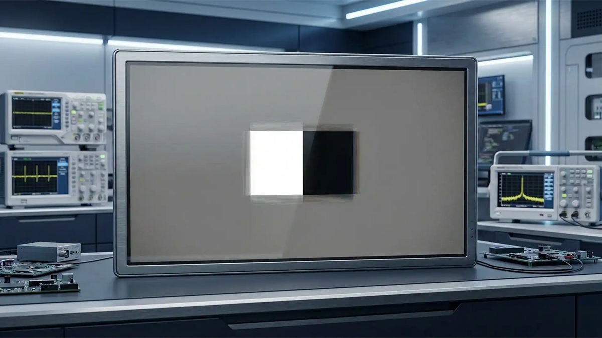
TFT LCD Crosstalk: Definition, Test Method, Causes and Improvement Solutions
TFT LCD crosstalk is a common but often underestimated display phenomenon. In practical use, users may notice that a gray region near a bright block, dark block, edge transition, or high-contrast graphic does not stay completely clean. Instead, that surrounding area can shift in brightness, show a faint shadow, develop directional contamination, or display a subtle ghost-like influence. This effect is usually described as crosstalk because one display region is unintentionally affecting another.
For display engineers, purchasing teams, OEM product managers, and system integrators, TFT LCD crosstalk should not be treated as a vague visual complaint only. It is also a technical sign of how stable the panel is under real electrical conditions. Crosstalk often reflects the balance between parasitic capacitance, TFT leakage current, storage capacitance, inversion mode, frame timing, and long-term reliability margin. If a screen shows visible crosstalk, there is usually a measurable electrical mechanism behind it.
This is why crosstalk matters in display module sourcing, panel evaluation, embedded design, HMI product development, medical equipment interfaces, handheld instruments, industrial controllers, and custom LCD projects. If the panel image looks contaminated in gray areas, the user may assume the product is lower quality even if the system still functions. In many B2B environments, that perception can influence approval, shipment, and long-term customer satisfaction.
In this complete guide, we will explain what TFT LCD crosstalk is, the difference between horizontal crosstalk and vertical crosstalk, how crosstalk is tested, how the result is calculated, what the main causes are, and what practical engineering methods can reduce it. We will also cover how buyers should evaluate crosstalk during supplier comparison and what questions should be confirmed before project approval. This long-form article is built to support both SEO and GEO by answering the most common technical and purchasing questions around TFT LCD crosstalk.
What Is TFT LCD Crosstalk?

Basic Definition
TFT LCD crosstalk refers to the unwanted influence of one image region on adjacent pixels or neighboring display areas. In a normal TFT LCD operation, each pixel should hold the correct voltage after it has been written and should produce the intended optical output until the next refresh cycle. Crosstalk appears when nearby electrical signals or retention instability disturb that stored voltage, causing a visible luminance difference that does not belong to the intended image.
In simpler terms, crosstalk means that the image displayed in one part of the panel is not fully independent from the image in another nearby part. This loss of independence can appear as brightness contamination, local shadows, vertical or horizontal influence, gray pollution, or a ghost-like pattern around a test object. The problem is especially visible when the image includes a strong contrast boundary, such as a white area surrounded by gray, or a black object placed in the middle of a medium-gray background.
Because TFT LCD image generation depends on accurate voltage control at the pixel level, even a relatively small disturbance in the stored pixel voltage can become visible. That is why crosstalk is not just a theoretical electrical issue. It has a direct optical result that users and customers can see during validation or in the final product.
Why Crosstalk Matters
Crosstalk matters because it affects both image quality and engineering confidence. A display with obvious crosstalk may still power on, show graphics, and pass basic functional checks, but it can still be judged as low quality because the image no longer looks clean. In applications such as medical interfaces, industrial control equipment, test instruments, portable terminals, or branded consumer hardware, the display is often one of the first elements users evaluate. If it looks unstable or contaminated, the entire product can appear less reliable.
From a technical perspective, crosstalk is valuable because it reveals whether the panel has enough margin in real operation. It can point to excessive coupling capacitance, insufficient storage capacitance, unstable TFT off-state behavior, unsuitable inversion mode, or parameter settings that need optimization. In other words, crosstalk is often a visible symptom of deeper electrical interaction. This is exactly why it deserves attention during design review and supplier qualification.
For purchasing teams, crosstalk also matters during vendor comparison. Two TFT LCD modules may look similar on the quotation sheet, with the same size, interface, resolution, and brightness, but one may control crosstalk better than the other because of stronger panel design or better drive tuning. That difference may only become clear during real testing, yet it can significantly affect final project satisfaction.
Why Crosstalk Is More Visible in Modern Displays
As TFT LCD technology continues to evolve toward higher resolution, smaller pixel pitch, thinner structures, and more compact routing, the electrical geometry inside the panel becomes denser. Conductive elements such as data lines, pixel electrodes, storage structures, and TFT-related nodes are placed closer together than in older designs. When structures become more crowded, parasitic electrical interaction becomes more difficult to suppress completely.
At the same time, many modern applications use cleaner UI designs, softer gray tones, sharper icons, and more demanding visual standards. These design choices make subtle image contamination easier to notice. A faint luminance shift that might once have gone unnoticed can now become visible because the product interface is expected to look more refined. This makes crosstalk a more important concern not only for display engineers but also for product teams focused on user perception and premium presentation.
Key point: TFT LCD crosstalk is both a visible image defect and an electrical-performance indicator involving pixel voltage interaction, retention stability, panel design margin, and drive condition suitability.
Types of Crosstalk in TFT LCD Panels

Horizontal Crosstalk
Horizontal crosstalk refers to display contamination that spreads mainly across the horizontal direction. In visual terms, the disturbance extends from left to right or right to left near a graphic edge, transition zone, or test pattern boundary. Depending on the panel structure and drive method, it may appear as a faint horizontal line effect, row-direction contamination, or local luminance imbalance.
Although horizontal crosstalk is sometimes discussed less than vertical crosstalk, it should not be ignored. In certain inversion modes, row-related timing strategies, or pattern structures, horizontal influence can become quite visible. It is especially relevant when the image content contains thin horizontal features or when a panel shows asymmetrical behavior between row-direction and column-direction image transitions.
Vertical Crosstalk
Vertical crosstalk refers to image contamination that spreads mainly in the vertical direction. This means the visual influence extends above and below the active image area. In many TFT LCD panel structures, vertical crosstalk is the more common and more intensively analyzed form because it is often strongly related to data-line coupling and TFT leakage-current behavior.
Since the data line usually runs in the column direction, any unwanted interaction involving the data line often produces a vertically distributed effect. For example, if the data-line voltage couples into nearby pixel nodes or if stored charge retention becomes unstable along a column-related path, the resulting optical contamination tends to appear vertically. This is why engineers frequently associate vertical crosstalk with parasitic coupling capacitance and off-state leakage current.
Difference Between Horizontal and Vertical Crosstalk
The most obvious difference lies in the visible direction of the artifact. However, the more important distinction is the underlying electrical path. Horizontal crosstalk often suggests row-direction influence, inversion interaction, or row-related timing effects. Vertical crosstalk more often suggests column-direction interaction, data-line coupling, leakage current, or retention imbalance. Correct classification saves time in debugging because it narrows down the likely root cause much faster.
In many real projects, the symptom may not be purely horizontal or purely vertical. Mixed behavior can occur, especially if multiple mechanisms are present. Even so, identifying the dominant direction still helps establish the first engineering hypothesis.
| Item | Horizontal Crosstalk | Vertical Crosstalk |
|---|---|---|
| Main visible direction | Left to right / right to left | Top to bottom / bottom to top |
| Typical association | Row interaction, inversion effect, timing balance | Column interaction, data-line coupling, TFT leakage |
| Common troubleshooting focus | Drive mode, row timing, pattern dependence | Cpd, Ioff, VGL, Cst, refresh rate |
| Visual pattern tendency | Spread across rows | Spread along columns |
How to Test TFT LCD Crosstalk

Common Test Images
A standard way to evaluate TFT LCD crosstalk is to use controlled gray-background test images. One common method uses a full 127 gray image as the baseline reference. This is then compared to images that add a white block or a black block in the center of the same 127 gray background. The purpose is simple: the surrounding gray region should remain neutral, so if it changes in luminance, the panel is showing crosstalk.
Some companies use a box-type pattern, while others use an I-type structure, a bar pattern, or a pattern customized to their own quality system. The exact image geometry may vary, but the engineering principle remains the same. A localized contrast target is inserted into a neutral field, and the neighboring region is measured to determine whether the display response is being unintentionally influenced.
This type of test is especially useful because it converts a subjective visual complaint into a measurable technical condition. Instead of saying that the screen “looks a little dirty,” engineers can define a repeatable image pattern, a measurement method, and an acceptance threshold.
Test Procedure
- Prepare the TFT LCD module, backlight condition, stable power input, and test fixture.
- Confirm that the image resolution exactly matches the native panel resolution.
- Display the full 127 gray image and allow the display to stabilize.
- Measure the luminance at predefined points in the area where crosstalk is expected to be observed.
- Display the 127 gray image with a central white block and measure the same points again.
- If black crosstalk also needs evaluation, display the 127 gray image with a central black block and repeat the measurements.
- Record all values carefully under consistent environmental conditions.
- Calculate the crosstalk percentage at each point.
- Compare the results with the customer requirement or internal quality limit.
For a meaningful result, the test should be performed with stable brightness settings, stable power, a controlled viewing angle, and enough settling time after each image switch. If the environment changes between measurements, the comparison becomes less reliable.
Measurement Points and Observation Logic
The measurement points are usually selected around the area most likely to be affected by the inserted pattern. For example, points may be placed above, below, left, and right of the central white or black object. In some systems these are labeled as P1, P2, P3, and P4. The exact location matters because crosstalk is often not uniform in all directions. A directional difference can help identify whether the root cause is more likely linked to a row path, a column path, or a localized structural feature.
Observation logic is just as important as raw measurement. If the defect becomes much stronger in the vertical direction than in the horizontal direction, the engineer should suspect data-line-related influence. If the crosstalk grows worse after thermal stress or long operating time, leakage-related behavior becomes more likely. If changing the inversion mode significantly changes the visual result, then the polarity relationship between neighboring pixels is probably contributing to the problem.
In high-level technical reviews, crosstalk analysis should combine numbers and visual evidence. Photos, luminance charts, and side-by-side comparisons under the same pattern often help customers understand the difference more clearly than percentages alone.
Calculation Method
White crosstalk is commonly calculated using the luminance difference between the white-block condition and the baseline gray condition at the same measurement point:
White Crosstalk (%) = |White_n − Gray_n| / Gray_n × 100%
Black crosstalk follows the same logic:
Black Crosstalk (%) = |Black_n − Gray_n| / Gray_n × 100%
This normalized percentage format is useful because it allows fair comparison even when different modules have different absolute luminance levels. It is also easier to include in specifications, validation reports, and supplier communication.
How to Judge the Results
The acceptable crosstalk limit depends on the customer standard, the application class, and the agreed visual target. In many projects, a value of not more than 2 percent is used as a control target. In some less demanding applications, not more than 3 percent may still be accepted. However, the number alone is not enough. The test pattern, measurement points, gray level, and environmental condition should all be confirmed clearly before the result is used for approval.
It is also important to evaluate the worst point, not only the average. One highly visible outlier can still lead to customer dissatisfaction even if the mean value looks acceptable. In B2B display projects, a disciplined point-by-point evaluation is usually more useful than a broad qualitative statement.
Testing principle: TFT LCD crosstalk is evaluated by comparing the luminance of the same location under a neutral gray condition and under a disturbed condition created by a central bright or dark image object.
Main Causes of TFT LCD Crosstalk

Coupling Capacitance Between Data Line and Pixel Electrode
One of the most important causes of TFT LCD crosstalk is parasitic coupling capacitance between the data line and the pixel electrode. Because these conductive structures are physically close inside the panel, a natural capacitance exists between them. This is often described as coupling capacitance or Cpd. When the data-line voltage changes during addressing, some of that change can couple into the pixel node and disturb the stored pixel voltage.
Even if the disturbance is electrically small, it can become optically visible because liquid crystal transmission is highly sensitive to voltage. This is especially true in medium-gray conditions, where a slight voltage shift may create a relatively visible luminance error. In many panel structures, this mechanism is one of the main reasons vertical crosstalk becomes visible.
As resolution increases and routing becomes denser, the design challenge grows. Tighter line spacing can improve pixel density and product compactness, but it also tends to increase the sensitivity to unwanted coupling. That is why panel structure optimization remains a key factor in crosstalk control.
TFT Leakage Current Ioff
TFT off-state leakage current, usually referred to as Ioff, is another major cause of crosstalk. After a pixel is charged, the TFT should ideally isolate it until the next frame update. In reality, no TFT is a perfect switch. A small leakage path usually remains. If that leakage current is too large, the stored charge on the pixel node gradually drifts, changing the actual pixel voltage before the next refresh cycle.
If the panel has strong retention stability, the voltage drift may stay small enough to remain invisible. But if leakage becomes significant, the resulting luminance deviation can be large enough to create visible crosstalk, particularly under high-contrast patterns. This effect is often more obvious in gray-background testing because medium gray is especially sensitive to voltage imbalance.
Leakage-current behavior can be influenced by TFT process quality, active-layer characteristics, gate insulation condition, panel aging, and reliability stress. Because of that, crosstalk linked to leakage current often points toward panel-side technology and long-term stability rather than a simple module assembly issue.
Storage Capacitance and Pixel Voltage Retention
Storage capacitance, often written as Cst, plays an important role in pixel voltage stability. A larger effective storage capacitance allows the pixel node to hold its voltage more firmly against small leakage effects or coupled disturbances. If the same amount of unwanted charge transfer occurs, the resulting voltage shift will be smaller when the storage capacitance is larger.
This is why insufficient or marginal storage behavior can contribute to crosstalk visibility. If the retention system is not robust enough, even moderate leakage or coupling can push the pixel voltage away from its intended level. In practical engineering, Cst is therefore closely related to crosstalk control, especially where voltage-holding stability is part of the root cause.
Drive Conditions and Reliability Environment
Panel structure is not the only factor. Drive conditions such as inversion mode, VGL, refresh rate, VCOM, gamma setting, and frame timing can all influence how visible crosstalk becomes. In many cases, a panel that looks acceptable under one driving condition can show stronger crosstalk under another. This is why application-side tuning must be considered during troubleshooting.
Environmental stress also matters. Elevated temperature, long-term operation, storage aging, and reliability testing can worsen off-state retention and leakage behavior. A module that passes early room-temperature evaluation may later show stronger crosstalk after stress testing. This does not mean the issue suddenly appeared from nowhere. It usually means the electrical margin was limited from the beginning and the stress condition made the weakness easier to see.
For this reason, crosstalk evaluation should ideally include not only initial measurement but also observation after key reliability conditions, especially in industrial and medical projects where stable long-term performance is important.
Crosstalk vs Other Display Defects
Crosstalk vs Flicker
Flicker is mainly a time-domain issue. The image appears to shimmer, pulse, or oscillate over time. Crosstalk is mainly a spatial issue, in which one image region influences nearby pixels. Although both can be related to panel drive conditions, they are not the same phenomenon. If the defect is tied to a fixed image edge or gray transition and stays in a stable location, crosstalk is more likely. If the display appears unstable over time even under a mostly uniform image, flicker should be investigated.
Crosstalk vs Mura
Mura usually refers to irregular nonuniformity such as cloudy regions, patchy brightness, or inconsistent optical texture. Mura often comes from optical variation, process texture, cell-gap irregularity, or backlight nonuniformity. Crosstalk is more pattern dependent and more directly linked to electrical interaction between neighboring image areas. If the defect appears only when a specific test object is shown and disappears under a uniform field, crosstalk is generally the better diagnosis.
Crosstalk vs Image Sticking
Image sticking or afterimage is a residual effect that remains visible after a previous image has been shown for a period of time. Crosstalk does not depend on residual memory in the same way. It appears while the disturbing image condition is active. If the effect disappears immediately when the pattern changes, crosstalk is more likely. If a previous image remains faintly visible after removal, image sticking should be considered instead.
Crosstalk vs Ghosting
The term ghosting is sometimes used loosely in the display industry, which can create confusion. In some contexts, customers use ghosting to describe any faint unwanted shadow around graphics. In a more precise engineering discussion, ghosting may describe image lag or residual traces, while crosstalk specifically describes unintended interaction between adjacent display regions. When communicating with customers, it is useful to define the symptom clearly rather than relying on a general term alone.
How to Reduce TFT LCD Crosstalk

Increase Data Line to Pixel Electrode Spacing
Increasing the spacing between the data line and the pixel electrode can reduce the parasitic coupling capacitance between them. This directly helps lower one of the main electrical paths behind vertical crosstalk. When the line and the pixel node are less tightly coupled, data-line voltage transitions are less likely to disturb the pixel voltage significantly.
However, this method involves trade-offs. Increased spacing may reduce aperture ratio, which can affect light transmission efficiency and optical performance. In panel design, crosstalk optimization is rarely free. Each electrical improvement must be balanced against brightness, resolution density, and structural constraints.
Change Inversion Mode
Changing the inversion mode is another effective method in some panel structures. For example, moving from column inversion to dot inversion can improve the local balance between adjacent pixels and reduce visible pattern-related crosstalk. By redistributing the polarity relationship more effectively, the panel may suppress the optical expression of electrical interaction.
This method can be powerful, but it may also increase power consumption or require different driver support. Therefore, it should be evaluated as part of the entire system rather than as a single isolated fix.
Adjust VGL Voltage
VGL influences the gate-off condition of the TFT. If the TFT is turned off more firmly, off-state leakage current may be reduced, and stored pixel voltage may remain more stable. This makes VGL tuning one of the most practical tools in crosstalk troubleshooting. If crosstalk changes significantly when VGL changes, the engineer gains strong evidence that leakage-related retention instability is a major part of the problem.
Of course, VGL must remain within the safe electrical margin of the panel and driver design. Aggressive adjustment without proper verification may introduce other risks. But as a controlled debug parameter, it is extremely useful.
Increase Refresh Rate
A higher refresh rate shortens the time between pixel rewrites. If leakage current is causing the pixel voltage to drift, a shorter frame period reduces the amount of drift that can accumulate before the next refresh. This is why increasing the refresh rate often improves leakage-related crosstalk performance.
The trade-off is that higher refresh rate increases interface bandwidth demand, controller workload, and often overall power consumption. Whether this is acceptable depends on the product type. In a mains-powered industrial HMI, higher refresh may be easy to accept. In a battery-powered handheld device, the trade-off may be more sensitive.
Increase Storage Capacitance Cst
Increasing storage capacitance improves the stability of the stored pixel voltage. If leakage current removes a certain amount of charge, the resulting voltage error will be smaller when the total capacitance is larger. This makes Cst a useful structural tool for reducing retention-related crosstalk.
As with other panel-level methods, there are design trade-offs. Larger storage structures may affect layout area, aperture ratio, and other panel parameters. Still, for panels where retention margin is critical, Cst optimization can be very valuable.
Optimize Panel Layout and Routing
Beyond single-parameter adjustment, overall panel layout optimization can also improve crosstalk. This includes better routing geometry, reduced overlap sensitivity, more balanced neighboring structure design, and improved shielding strategy where applicable. In some cases, crosstalk is not caused by one isolated issue but by the combination of several marginal layout factors. A holistic review of the panel architecture can therefore provide the best long-term solution.
For suppliers developing custom panel programs or deeply optimized modules, layout-level control is often what separates a merely functional display from a high-quality display.
| Improvement Method | Main Benefit | Possible Trade-Off | Typical Level |
|---|---|---|---|
| Increase spacing | Reduce coupling capacitance | May reduce aperture ratio | Panel design |
| Change inversion mode | Improve adjacent-pixel balance | May increase power consumption | Driver / panel strategy |
| Adjust VGL | Reduce TFT leakage influence | Needs electrical margin verification | Module / system tuning |
| Increase refresh rate | Reduce voltage-drift time | Higher bandwidth and power | System tuning |
| Increase Cst | Improve retention stability | Layout and optical trade-off | Panel design |
| Optimize routing layout | Lower combined parasitic sensitivity | Requires panel redesign effort | Panel design |
Practical Engineering Workflow

Customer-Side Symptom Confirmation
When a customer reports a suspected TFT LCD crosstalk issue, the first step is to confirm the symptom accurately. The supplier should ask for the test image, gray level, refresh rate, brightness setting, ambient temperature, power condition, and visual evidence such as photos or video. It is also useful to ask whether the defect appears only in one pattern, one operating mode, or one temperature range.
Many discussions become inefficient because the initial complaint is too general. Terms like “dirty display,” “shadow,” or “abnormal gray” are not enough. A repeatable pattern-based condition is needed before the issue can be analyzed correctly.
Module-Side Parameter Verification
Once the symptom is reproduced, the next step is module-level parameter review. Important items include VGL, VGH, VCOM, inversion mode, frame rate, gamma setting, and interface timing. If the result changes after one of these adjustments, the engineering direction becomes much clearer. This stage is particularly important in custom application projects, where the same panel may behave differently under different mainboard or firmware conditions.
At this stage, it is also useful to compare the module against a known-good sample or evaluation board. If the crosstalk difference is large under the same pattern, the application-side settings may be the main issue rather than the panel structure alone.
Panel-Side Root Cause Analysis
If module-level tuning is not enough, the problem should be escalated to panel-side analysis. This means reviewing coupling capacitance paths, line spacing, overlap geometry, TFT leakage-current behavior, storage capacitance design, and performance after reliability stress. At this point, the engineering goal is to determine whether the problem is structural, process related, aging sensitive, or application driven.
Panel-side analysis is especially important when the crosstalk result worsens after temperature aging or when VGL tuning strongly affects the symptom. Those signs often indicate that retention stability and leakage current are major contributors.
Verification After Improvement
After any improvement action, the result should be verified using the same test pattern, same luminance method, and same environmental setup as the original evaluation. Without this consistency, it becomes difficult to judge whether the improvement is real or just the result of changed conditions. Ideally, the before-and-after comparison should include both quantitative measurement and visual images.
For long-term project confidence, the improved condition should also be checked under key reliability or temperature states if those are relevant to the end application. A fix that works only at room temperature may not be enough for industrial deployment.
Application and Sourcing Considerations

Why Buyers Should Care About Crosstalk
Buyers should care about TFT LCD crosstalk because it directly affects product appearance, user perception, and quality consistency. A module that meets brightness and resolution requirements on paper may still underperform visually if gray areas look contaminated or if high-contrast UI elements create unwanted shadows. In industrial equipment, medical devices, smart terminals, and embedded control systems, this can reduce the perceived professionalism of the final product.
Crosstalk is also an indicator of engineering maturity. Better crosstalk control often reflects stronger panel optimization, more stable electrical behavior, and better supplier understanding of display quality. When comparing suppliers, this can become an important differentiator that is not obvious from a simple specification table.
What to Confirm With Suppliers
When evaluating a TFT LCD supplier, buyers should confirm how crosstalk is tested, what image pattern is used, what gray level is used as the reference, how the result is calculated, and what acceptance limit is being applied. It is also useful to ask whether the result was checked only at room temperature or also after reliability stress such as high-temperature aging.
In addition, buyers should ask whether module-level tuning is possible. Parameters such as VGL, VCOM, inversion mode, and refresh rate can sometimes be adjusted during application development. If the supplier understands these tuning paths and can support debugging, project risk becomes easier to manage.
Recommended Questions Before Approval
- What is the exact crosstalk test image and gray-level condition?
- What are the measurement points and the calculation formula?
- What pass/fail limit is used for this panel or module?
- Was the result verified only at room temperature or also after reliability testing?
- Can VGL, refresh rate, or inversion mode be tuned if application-side optimization is required?
- Is the observed crosstalk mainly vertical, horizontal, or mixed?
- Does the supplier have previous experience solving similar image-quality issues in mass-production projects?
Need a Stable TFT LCD Module for Your Project?
If you are selecting TFT LCD modules for industrial equipment, embedded systems, medical devices, handheld terminals, instrumentation, or custom applications, you can place internal links here to your TFT LCD category pages, IPS TFT pages, custom LCD development page, touch panel integration page, or inquiry page.
Suggested internal links: TFT LCD Modules / IPS TFT Displays / Custom LCD Solutions / Touch Panel Integration / Contact Us
SEO and GEO Summary for Technical Buyers
If you are searching for what TFT LCD crosstalk means, how vertical crosstalk is tested, what causes TFT LCD crosstalk, or how to reduce crosstalk in a TFT panel, the answer is that crosstalk is usually a combination of panel structure, parasitic coupling, charge retention behavior, and driving conditions. The most common mechanisms are coupling capacitance between the data line and pixel electrode, excessive TFT off-state leakage current, insufficient voltage-holding stability, and parameter settings that make the defect more visible.
If you are comparing TFT LCD suppliers, ask them for a clear crosstalk test method, actual image pattern, measurement standard, and whether the result was checked after stress or long-term reliability conditions. If you are debugging a field problem, start by confirming whether the artifact is really crosstalk or whether it is actually flicker, mura, image sticking, or general ghosting. If you are designing a new product, evaluate crosstalk early so that image-quality expectations are aligned before mass-production approval.
In short, TFT LCD crosstalk is not a minor side topic. It is a practical display-quality parameter that affects engineering decisions, customer evaluation, and final product performance.
Conclusion
TFT LCD crosstalk is an important image-quality topic in modern display engineering. It occurs when one image region unintentionally influences neighboring pixels, producing local contamination, luminance error, or directional shadow-like effects. In practical analysis, it is usually categorized into horizontal crosstalk and vertical crosstalk, with vertical crosstalk often more strongly associated with data-line coupling capacitance and TFT leakage current.
Understanding crosstalk requires both electrical and optical thinking. The issue is visible on the screen, but the mechanism behind it usually involves panel geometry, parasitic capacitance, charge retention, storage capacitance, inversion strategy, drive voltage settings, refresh timing, and reliability behavior. This is why structured testing is essential. A good crosstalk evaluation should use defined patterns, consistent measurement points, percentage-based calculation, and agreed acceptance criteria.
In improvement work, there is no single universal fix. Depending on the root cause, engineers may reduce crosstalk by increasing data-line spacing, changing inversion mode, adjusting VGL, increasing refresh rate, enlarging storage capacitance, or optimizing the panel layout itself. The correct solution depends on whether the problem is structural, parameter related, or stress induced.
For both buyers and suppliers, the best approach is to treat crosstalk as a real technical parameter from the beginning. When it is discussed early, measured clearly, and optimized with the right engineering logic, it becomes much easier to select the right TFT LCD solution and avoid quality disputes later in the project.
FAQ
What is TFT LCD crosstalk?
TFT LCD crosstalk is a display phenomenon in which one image area unintentionally affects neighboring pixels, causing local luminance contamination, gray distortion, or a ghost-like influence around the original image.
What causes vertical crosstalk in a TFT LCD panel?
Vertical crosstalk is commonly related to coupling capacitance between the data line and the pixel electrode, TFT off-state leakage current, storage behavior, and drive conditions that make column-direction interaction more visible.
What is the difference between horizontal crosstalk and vertical crosstalk?
Horizontal crosstalk mainly spreads across the horizontal direction, while vertical crosstalk mainly spreads in the vertical direction. The two often suggest different electrical interaction paths inside the panel.
How do you test TFT LCD crosstalk?
Crosstalk is usually tested with a 127 gray reference image and disturbed images containing a central white or black block. Luminance is measured at defined points and compared with the gray baseline to calculate the crosstalk percentage.
What is the formula for TFT LCD crosstalk calculation?
A common formula is \( |White_n - Gray_n| / Gray_n \times 100\% \) for white crosstalk, and the same structure is used for black crosstalk with the black-pattern measurement value.
What crosstalk level is usually acceptable?
Many projects control TFT LCD crosstalk at not more than 2 percent, while some applications may allow up to 3 percent depending on the use case and customer standard.
Can VGL adjustment reduce TFT LCD crosstalk?
Yes. If the main issue is related to TFT off-state leakage current, adjusting VGL can improve the gate-off condition, reduce leakage influence, and help suppress visible crosstalk.
Does a higher refresh rate help reduce crosstalk?
In many cases, yes. A higher refresh rate reduces the time available for stored pixel voltage to drift before the next rewrite cycle, which can improve leakage-related crosstalk behavior.
Why is TFT leakage current important in crosstalk analysis?
If TFT off-state leakage current is too high, the stored pixel charge cannot remain stable between refresh cycles. This voltage drift can create visible luminance error and worsen crosstalk, especially in medium-gray conditions.
How is crosstalk different from flicker?
Flicker is mainly a time-based instability, while crosstalk is mainly a spatial interaction between adjacent image regions. The two may share some drive-related causes, but they are different display defects.
How is crosstalk different from mura?
Mura is usually a broader nonuniformity issue such as patchy or cloudy appearance, while crosstalk is more specifically linked to the effect of one image region on neighboring regions under a defined pattern.
What should buyers ask suppliers about TFT LCD crosstalk?
Buyers should ask about the test image, gray level, measurement method, calculation formula, pass/fail limit, reliability verification condition, and whether tuning options such as VGL or refresh rate are available during integration.


댓글 남기기
이 사이트는 hCaptcha에 의해 보호되며, hCaptcha의 개인 정보 보호 정책 과 서비스 약관 이 적용됩니다.